
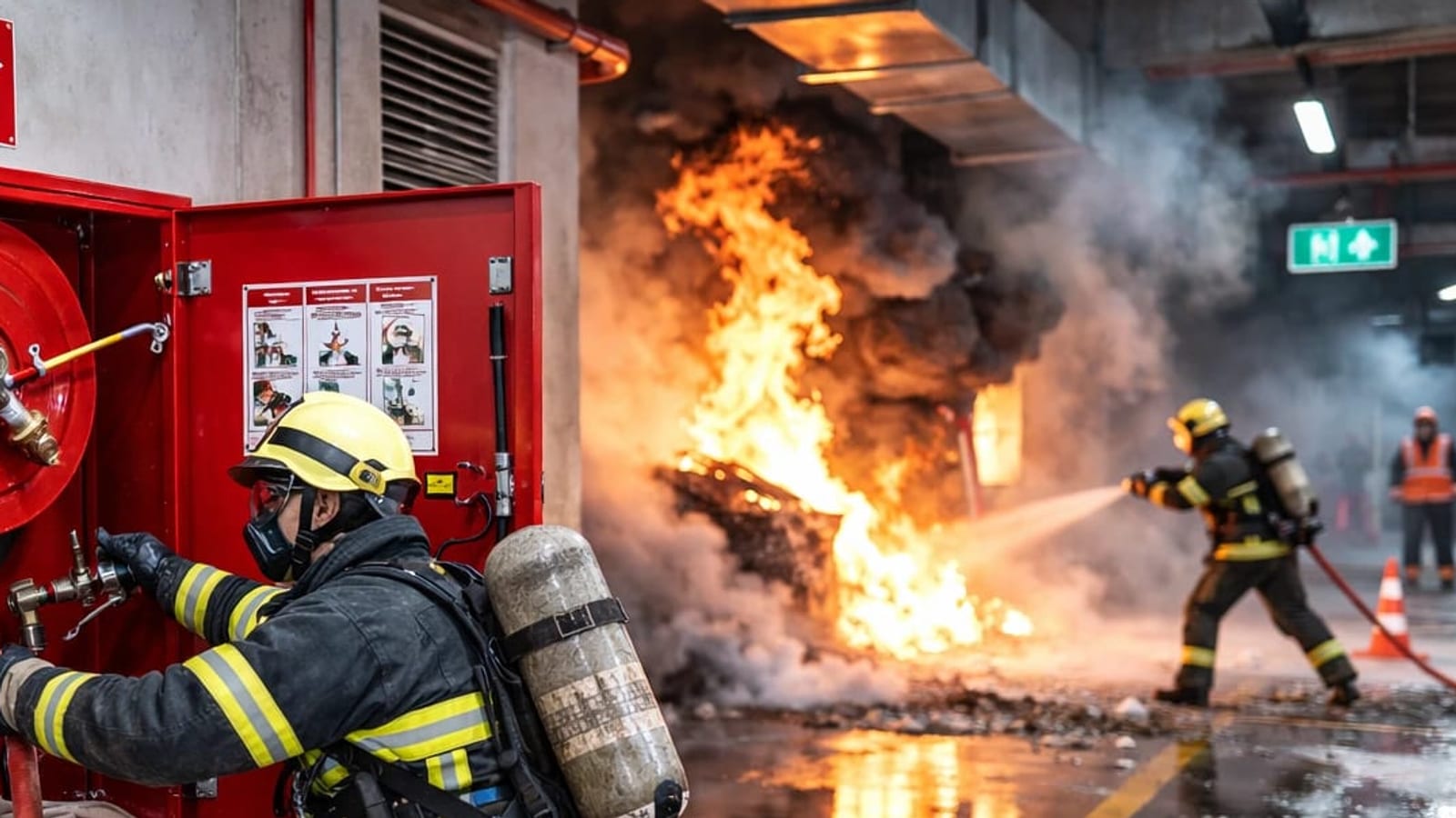
Fire cabinets and hydrants differ from fixed extinguishing systems at one point: they do not operate automatically; someone must use them. For this reason, the design of these systems is as much about human behavior as it is about hydraulic calculations — where the cabinet is located, whether the hose can be pulled by one person alone, and whether the pressure at the nozzle pushes the person back or not, is more determinative than the flow rate on paper.
Cabinet types and where each should be used
| Type | Standard | Characteristic | Suitable for |
|---|---|---|---|
| Wheeled, fixed-outlet hose cabinet | TS EN 671-1 | Semi-rigid hose wound on reel; delivers water as it is pulled out | Untrained users, hotels, shopping centers, offices, residential buildings, hospitals |
| Flat hose cabinet | TS EN 671-2 | Delivers higher flow rate; the hose must be completely unrolled to be usable | Industrial facilities with trained personnel, fire department intervention points |
A common mistake we observe in the field is the installation of flat hose cabinets on office floors. Technically it delivers a higher flow rate; in practice, no one in the building can fully unroll and use a twenty-meter flat hose during a fire. Cabinet selection made without determining the user profile leaves the system non-functional on first use.
Pressure and flow rate
Two limits must be provided simultaneously in the fire cabinet system:
- Lower limit. At the cabinet in the most unfavorable location, the required flow rate and pressure must be provided when the planned number of cabinets are opened simultaneously. Hydraulic calculation is performed from this point.
- Upper limit. At the cabinet in the most favorable location (usually at the lowest floor), pressure must not exceed the value at which the hose and nozzle can be safely used.
In multi-story buildings, providing both limits simultaneously at lower floors pressure reducer requires use of a. In projects without pressure reducers, lower floor cabinets appear "more than adequate" when measured; in actual use the hose goes out of control. Values are determined according to the building's use classification and applicable regulations, calculated during the design phase.
Placement
- Access distance. Under BYKHY, the distance between cabinets on each floor and in each section separated by fire walls does not exceed 30 m; if the building is protected by a sprinkler system and fire brigade water outlets are provided on the floors, it may be increased to 45 m (Article 94). Within this limit, every point of the protected area must be reachable with the hose; hose length and effective water jet distance are evaluated together.
- On escape routes. Cabinets are placed at points the user will encounter while moving in the escape direction — stairwell landing, corridor junction, exit vicinity. A cabinet that requires the user to turn back away from escape is an unused cabinet.
- Front must remain clear. Pallets in storage, vehicles in parking lots, materials placed in front of cabinets in corridors — these are the system's most frequently encountered actual failures. Floor marking is a simple and effective solution.
- Visibility and marking. The cabinet location must be marked so it can be found even when lighting is cut off.
Hydrant system
Hydrants enable the fire department to intervene from outside the building and are typically fed by a separate line from the building's internal cabinet system.
- Above-ground hydrant. It is easy to locate and connect; it must be protected against vehicle impact and breakaway body type should be preferred.
- Underground hydrant. BYKHY Article 95/6 requires above-ground fire hydrants complying with the relevant Turkish Standards in a hydrant system; an underground hydrant does not count as a hydrant of this system. For underground hydrants in existing facilities, the cover access must be kept continuously clear and the location must be marked. Underground hydrants covered by snow, soil or asphalt are considered non-existent.
- Placement. Distance between hydrants and distance from building are determined by regulations according to the building's use classification and risk status; spacing is kept shorter in high-risk facilities.
- Connection coupling compatibility. Coupling type must be compatible with the connection used by the fire department in the region. Incompatible coupling means minutes spent searching for an adapter on site.
Fire department connection (siamese connection)
An external connection is provided so the fire truck's own pump can feed the building's sprinkler or hydrant line. This connection must be accessible, marked, equipped with check valve, and have the correct coupling. One of the most frequently identified deficiencies in compliance inspections is a fire department connection blocked by parking areas or landscaping.
Relationship with water source
The cabinet and hydrant system depend on the tank and fire pump capacity. Tank volume is calculated based on the system's ability to operate for the planned duration; if a sprinkler system is fed from the same tank, requirements are evaluated together. In systems fed directly from the city water network, the availability of network pressure and flow during a fire must be verified — a network value measured during the day may not be valid at night or during summer peak.
Periodic testing and maintenance
In annual inspection, the hose at each cabinet is completely opened and water is supplied, nozzle operation is tested, the hose is checked for cracks and aging, valve tightness is inspected, and pressure-flow measurement is performed at the most unfavorable point and recorded. At hydrants, cover and body access, drainage, and coupling condition are checked. TS EN 671-3 defines the essentials regarding maintenance of cabinets and hose reels; subjecting hoses to pressure testing at specified intervals falls within this scope.
For details on our maintenance scope, refer to our fire cabinet and hydrant maintenance page; for assembly and connection details, refer to our fire cabinet installation may be consulted.
Yeraltı besleme hattı
Hidrantları besleyen hat çoğu projede toprak altında ve PE (polietilen) borudur. Bu hatta ek yerleri contalı değil füzyon kaynağıyla yapılır: ısıtılan boru uçları basınç altında birleşir ve bağlantı boru malzemesiyle aynı yapıya gelir. Gömülü bir hatta kaçağın ancak basınç düştüğünde fark edildiği düşünülürse, ek yerinin borunun kendisi kadar sağlam olması tasarımın sessiz ama belirleyici parçasıdır.
Project and product
For fire cabinets, hose reels, hydrants, valves, and fire department connections, refer to our fire cabinet and hydrant product group ; for placement and hydraulic calculation support for your building, please contact us.
Frequently Asked Questions
What is the difference between a reel-type fire cabinet and a flat-hose cabinet?
In the reel cabinet (TS EN 671-1), semi-rigid hose is wound on a drum and delivers water as it is pulled; it can be used by a single person without training. In the flat-hose cabinet (TS EN 671-2), higher flow rates are achieved but the hose must be completely unrolled. The reel type is preferred in buildings with untrained users.
What should the pressure be in a fire cabinet?
Two conditions must be met together: the cabinet at the most unfavorable point must provide the required flow rate and pressure, and the cabinet at the most favorable point must not exceed the safe pressure value for use. In multi-story buildings, this requires the use of pressure reducers in lower floors. The values are calculated during the design phase based on the building's occupancy classification and applicable regulations.
How is the spacing between fire cabinets determined?
Under BYKHY, the distance between cabinets on each floor and in each fire section does not exceed 30 m; in a building with sprinklers and fire brigade water outlets on its floors it may be increased to 45 m. Within this limit, the principle is that every point of the protected area must be reachable by hose; the spacing is determined by evaluating hose length and effective water jet distance together. Cabinets must be located on escape routes at points where users will encounter them in the direction of escape, and their fronts must be kept continuously clear.
What is the purpose of the fire department connection?
It allows the fire department vehicle to supply the sprinkler or hydrant line inside the building with its own pump. It must be accessible, marked, equipped with a check valve, and compatible with the coupling used by the local fire department. A fire department connection with its front blocked by parking areas or landscaping is a deficiency frequently identified during compliance inspections.
What is done during fire cabinet maintenance?
The hose is fully extended and water is supplied, nozzle operation is tested, the hose is checked for cracks and aging, valve tightness is verified, and pressure-flow measurements are taken and recorded at the most unfavorable point. On hydrants, cap access, drainage, and coupling condition are checked; hoses are subjected to pressure testing at specified intervals.