
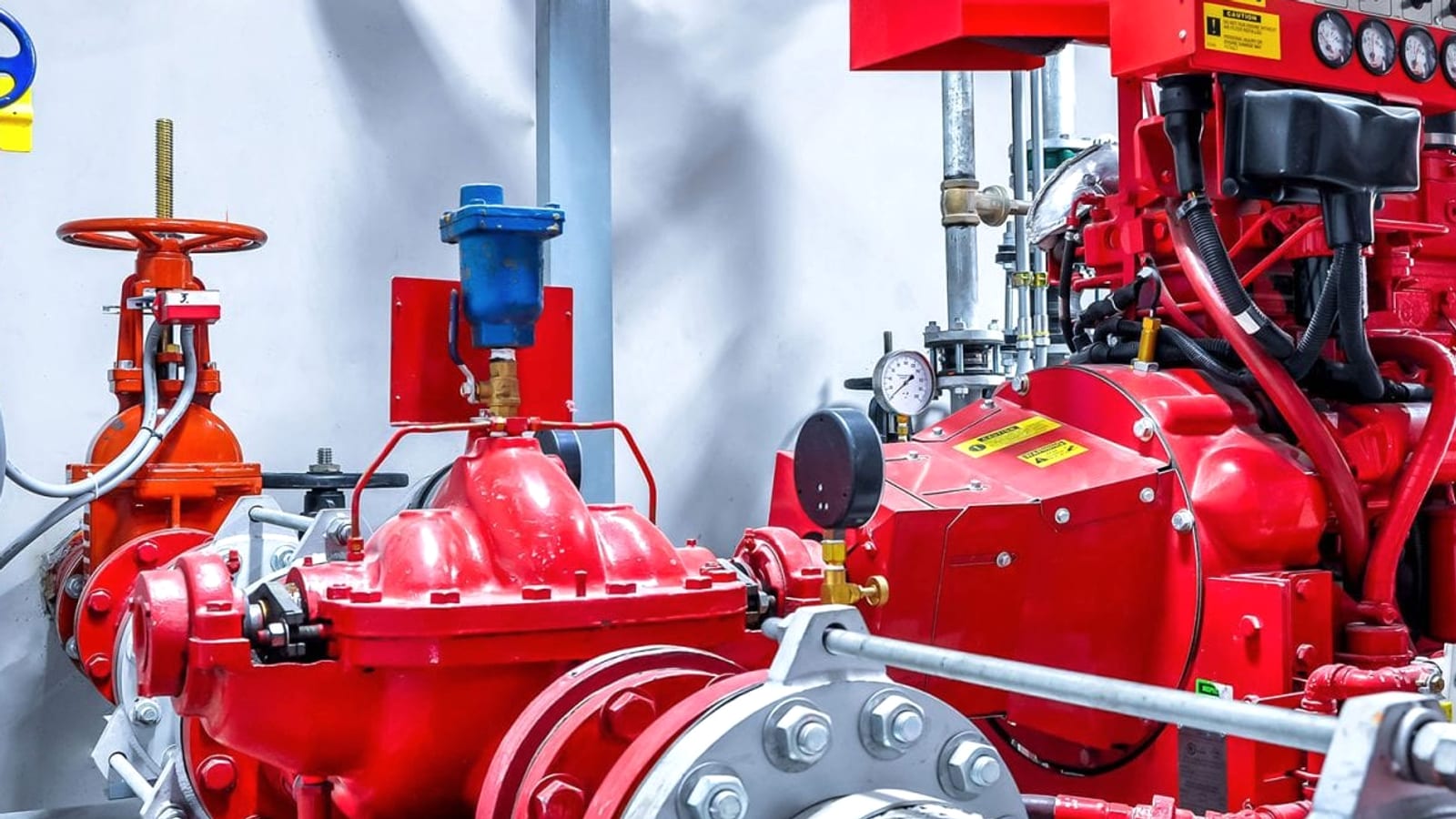
Sprinklers, hydrants and fire cabinets — the entirety of water suppression depends on a single machine. If the fire pump fails, the million-dollar pipe network behind it becomes worthless. This is why the fire pump is chosen not by its flow rate but by its reliability: once a year, in the middle of a night when it has not operated, it is expected to start on the first attempt.
Why is the pump group three-part?
| Pump | Function | Attention |
|---|---|---|
| Main pump (electric) | Provides the system design flow rate and pressure | Power supply is drawn independently from the main panel and shall not be cut off in case of fire |
| Backup pump (diesel) | Engages when electric power is lost or the main pump fails | Without fuel, battery, exhaust, and ventilation solutions, diesel pump reliability is not assured |
| Jockey (pressure maintenance) | Compensates for pressure drop caused by minor leaks in the line | Low flow is selected; oversized jockey may mask an actual activation |
In some cases where electrical power supply is reliable and regulations permit, the backup pump may also be electric; in this case it must be documented that the two pumps are truly independently powered. Two electric pumps fed from the same panel represent a second pump, not redundancy. Regarding ZQX0ZQX and ZQX1ZQX: which standard to follow
NFPA 20 and EN 12845: which standard to follow
Projects in Turkey reference both standards, and they differ at certain points. At project inception, which standard shall serve as the basis must be determined in writing; otherwise continuous conflicts arise during manufacturing, installation, and acceptance phases.
In practice, notable differences appear in the following areas: suction arrangement and pump location relative to water source, fire resistance and separation of pump room, test arrangement and acceptance criteria, diesel motor requirements, and control panel behavior. The insurance company's or employer's specification most often determines this choice.
What does UL / FM approval mean
For a fire pump and motor to be UL listed or FM approved means the equipment has been tested for fire service by an independent body. This approval is most often sought jointly for the pump, motor, and control panel assembly — approval of the pump body alone does not mean the assembly is approved. Clear distinction of this in the specification is the most useful item in tender comparison.
Basis of selection: pump curve
A fire pump is selected not according to a single flow-pressure point, but according to its entire curve . Common practice is that the pump shall deliver at least 65% of rated pressure at 150% of rated flow. The reason is that in a real fire, more nozzles may be opened than designed for, and the system must produce sufficient pressure at that point.
Closed valve (zero flow) pressure is also important: excessively high closed valve pressure stresses the pressure class of pipes and fittings and may even require a pressure reducer. Selection is calculated working backward from the required pressure at the farthest and highest point of the system.
Suction side: most frequent error
- Positive suction is preferred. Having the reservoir water level above the pump axis ensures the system remains self-primed. Arrangements working with suction lift require additional priming and vacuum solutions.
- The suction pipe shall be short and straight. An elbow immediately upstream of the pump inlet disturbs flow and causes cavitation.
- Reducer shall be eccentric. Concentric reducer leaves an air pocket at the pipe crown; eccentric reducer is installed with flat side up.
- Anti-vortex device is required. Whirl at the reservoir outlet draws air into the pump.
- Butterfly valve shall not be used in suction line. Even in fully open position it obstructs flow; slide valve is preferred and locked in open position.
Pump room
The volume housing the pump itself is as much part of the design as the pump:
- Fire resistance and separation. Pump room shall be separated so as not to be affected by fire in the building it protects.
- Ventilation. Diesel motor requires both combustion air and cooling air; duct cross-section is calculated according to motor power. Insufficient ventilation is the most common cause of diesel pump shutdown under load.
- Exhaust. Discharged outdoors, with non-combustible material and without exceeding back pressure limit.
- Fuel. Daily fuel tank capacity shall meet the operating duration required by the applicable standard; fuel aging and water accumulation shall be monitored.
- Heating and freeze protection. A frozen line renders a working pump inoperative.
- Drainage. Discharge of water drained during testing must be resolved; if not resolved, tests become impossible.
Test arrangement
A fire pump shall be testable at real flow. For this, either a closed-loop test line with flow meter or a test manifold allowing measurement via hydrant nozzles is provided. A pump room without test arrangement cannot perform annual performance tests; the system is only checked at "is it running" level and pump curve degradation is never detected.
Operating and stopping logic
Fire pump engages automaticallyvia a pressure switch sensing pressure drop in the line. Stopping is manual. This is a rule that shall not be debated in design: automatic pump shutdown when pressure rises may cause system cutoff while fire persists.
The control panel additionally contains weekly automatic operation (test) logic, phase and supply monitoring, and on the diesel side battery charging and starter circuit monitoring. Fault signals generated by the panel must be transmitted to the facility's fire detection panel — a fault lamp burning alone in the pump room conveys no information unless someone sees it.
Commissioning and periodic testing
During commissioning, the pump performance curve is measured and compared with manufacturer's curve, automatic operation scenarios are tested separately for both pumps, diesel motor is run under load for the specified duration, and all records are entered in the report. This initial record is the only reference for detecting performance loss in subsequent years.
For scope and frequency of periodic tests, fire pump maintenance refer to our page. For standard aspects of pump selection, NFPA 20 and UL/FM approval, and for pump room design, our article on pump room design may be consulted.
Project and product
For electric and diesel fire pump groups, jockey pumps, and control panels, refer to our fire pump product group , and for flow-pressure calculation and pump room assessment for your facility, contact usA zone monitoring module connects an entire conventional detector line to the addressable loop. Critical areas are renewed with addressable devices while secondary zones continue to operate with their existing wiring. This provides significant cost advantage in capacity upgrade and renovation projects.
Frequently Asked Questions
How to select a fire pump?
Selection is calculated backward from the required flow and pressure at the farthest and highest point of the system. The entire pump curve is evaluated, not a single point: the widely accepted criterion is that at 150% of rated flow, at least 65% of rated pressure is maintained. It is also verified that the closed valve pressure does not exceed the pressure class of the piping and fittings.
Why is a diesel fire pump necessary?
It provides redundancy against the possibility of loss of electrical power during a fire. For the diesel pump to be considered reliable, fuel capacity, battery and starter circuit, combustion and cooling air supply, and exhaust solution must all be complete; inadequate ventilation is the most common cause of diesel pump shutdown under load.
What is the purpose of the jockey pump?
It compensates for pressure drop caused by minor leaks in the line, preventing unnecessary activation of the main pump. It is selected for low flow. Frequent operation of the jockey should not be considered normal; it indicates a leak in the system and its source must be investigated.
Why does the fire pump not stop automatically?
It starts automatically when pressure drops, but stopping is done manually. Automatic shutdown when pressure rises could cause the system to be shut down while a fire is ongoing. Configuring automatic shutdown logic is one of the most dangerous errors in fire pump design.
What should be observed regarding the pump suction line?
Positive suction is preferred, the suction pipe is kept short and straight, an elbow is not placed immediately before the pump inlet, eccentric reduction is selected and installed with the flat side facing upward, a vortex preventer is placed at the tank outlet, and a gate valve is used instead of a butterfly valve in the suction line and locked in the open position.